Atlanta Airport APM Tunnel Extension
Hartsfield-Jackson Atlanta International Airport, GA (2020)
The existing Automated People Mover under an operational terminal was extended westwards by about 660 ft with a tail branching to reduce turnaround times and increase capacity. The project included:
♦Construction shaft 30 ft inside diameter and 60 ft deep to start the tunnel construction and be used as emergency exit after completion. Initial support was provided by secant piles on a circular perimeter and the final lining was cast in-place.
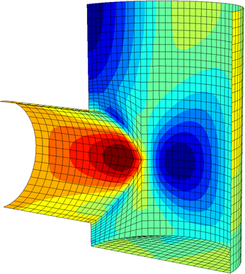
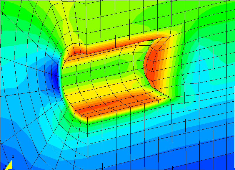
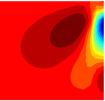
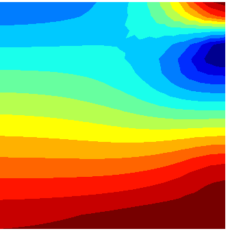
♦Single-track tunnel starting from the shaft with a variable mixed face in saprolite and rock. It then bifurcates under shallow rock to twin single- track tunnels in saprolite to connect to the existing tunnels under the live terminal. Initial shotcrete lining and rock bolts stabilized the tunnel excavation during construction. The widening bifurcation section had only 5-7 ft of rock cover. Special support classes were developed using 3D analyses of the shallow rock cover.
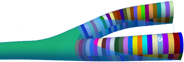
Above: Flac 3D model of the bifurcation and mixed face tunnels. Ground domain not shown. Opposite: Flac 3D model of the shaft and tunnel, UDEC analysis of the section with shallow rock cover, shell model of the construction shaft.
Don Yard Approach Structure
Ontario Subway Line, Toronto, Canada (2021)
The subway line changes from surface to underground in the Don Yard by a ramp ranging in depth from 0 to 10m. The ramp is adjacent to four tracks of rail transit, which imposed tight deformation limits. Design works included:
♦Study of the liquefaction potential of the weak soil layers on the site extending to below the bottom of excavation. Empirical methods were used as well as non-linear site response analysis using the Deepsoil program.
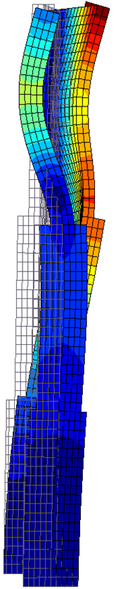
♦Design of the retaining system consisting of secant piles, prestressed tiebacks and steel struts. The design was based on soil-structure analyses considering stages of construction and groundwater flow.
Route 121/460 Poplar Creek Bridge
Buchanan County, Virginia (2024)
Design review and independent calculations of a 1100 ft long and 70 ft wide bridge supported by three intermediate pillars reaching 155 ft in height:
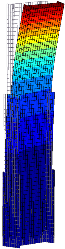
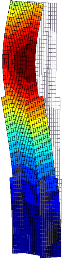
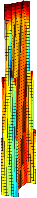
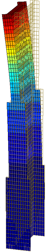
♦Check of the pillar stability using linear buckling (eigenvalue) analyses. Check of pillar strength under vertical and lateral loads by geometric and material non-linear analysis considering geometric imperfections.
♦Seismic analysis using the response spectrum method.
♦Check of rock cut stability under the left abutment. Study of rock joint orientation and modification of design according to the outcome of FEA with Hoek-Brown rock material model.
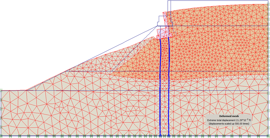
♦Check of the right abutment stability built on fill and supported by micro-piles using soil-structure interaction analysis.
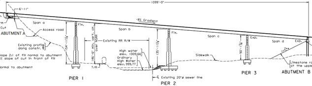
Above: Bridge profile across Levisa Fork. Opposite: The first 3 buckling forms of the highest pillar, vertical stress under H+V loads with geometric and material non-linearity. Plaxis 2D model of the embankment under the right abutment supported on micro-piles.
Eglinton Subway Stations
Toronto Transit, ON, Canada (2017)
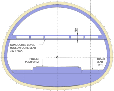
The Eglinton line in Toronto includes 3 stations mined by the SEM with an ovoid cross section. A complete structural design was produced for the concourse slab and interior structures. The concourse slab spans 15 m freely between the side walls and includes several large openings for stairs, escalators and elevators.
♦An efficient and innovative structural system for the concourse slab used 750 mm thick cast in-place hollow core slab monolithically connected to the permanent Cast in-place RC lining to reduce the self- weight and limit the structural depth while satisfying strength and deflection requirements. Only 4 steel columns around the elevator opening were used, while the rest of the station length had no intermediate supports.
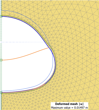
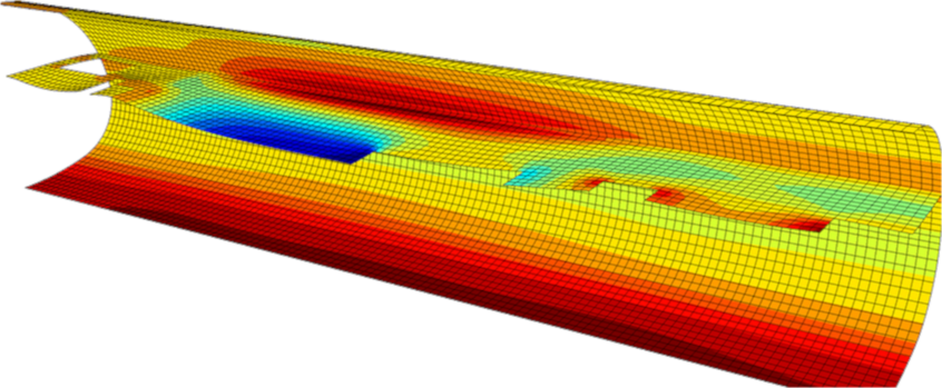
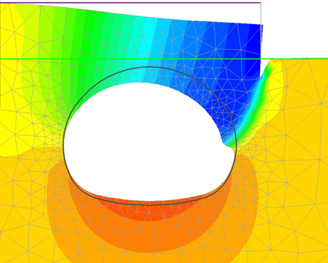
♦Structural design included an elastically supported 3D FE model that reflected the interaction of the final lining with the surrounding soil as well as the varying groundwater table.
Opposite: Station cross section, interaction between the concourse slab and surrounding soil, 3D shell model of the concourse slab and permanent lining.
Confederation Subway Line
Ottawa Light Rail Transit, ON, Canada (2015)
The underground reach of this line consisted of a 2.4km long two-track running tunnel and 3 subway stations and was constructed by the SEM.
♦The tunnel is 10m wide between spring lines with the crown 12-26m below ground surface. It was driven in the local Verulam and Lindsay sedimentary rock formations by roadheaders and supported by a GFRP-reinforced initial shotcrete lining and rock bolts. A special support class was designed for a 60m long part completely in soft ground of glacial tills.
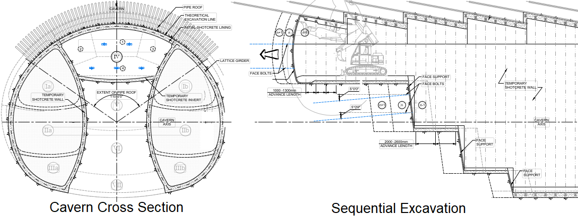
♦Rideau underground station is 20m wide between spring lines and 12m below ground surface. The west part is in soft ground and connects to the running tunnel and escalator tunnel by a domed headwall. The cavern was excavated in multi-drift headings and supported by a thick shotcrete lining after stabilizing the roof by a pipe umbrella.
♦Design of both units was based on 2D Finite Element/Distinct Element Analyses for typical sections and 3D FEA for parts connected to access shafts, escalator tunnel or utility adits.
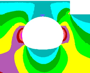
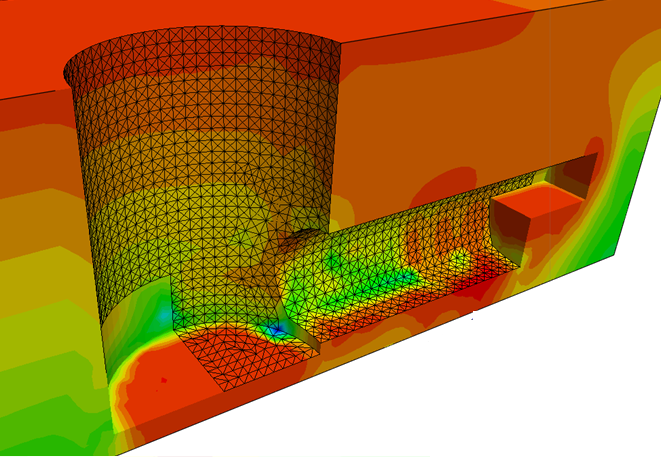
Above: Factor of safety analysis of the cavern section in rock with an existing basement excavation, DEA of jointed rock (UDEC) around the cavers at the same section.
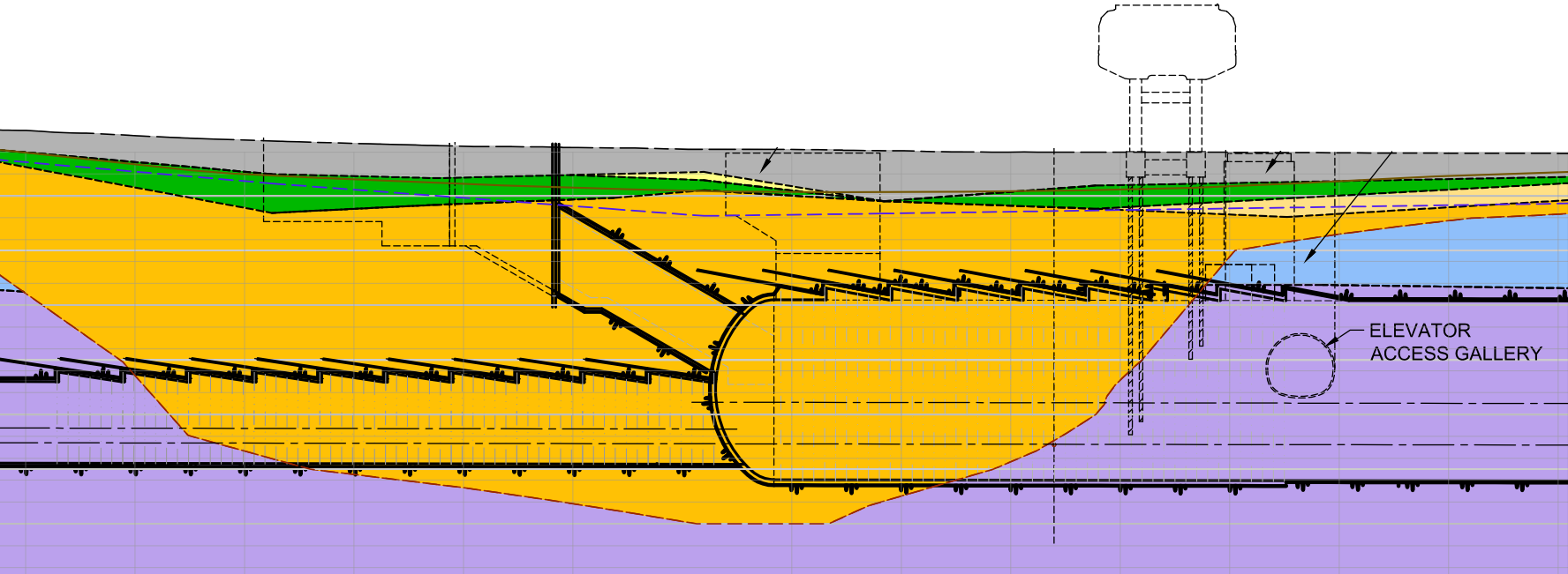
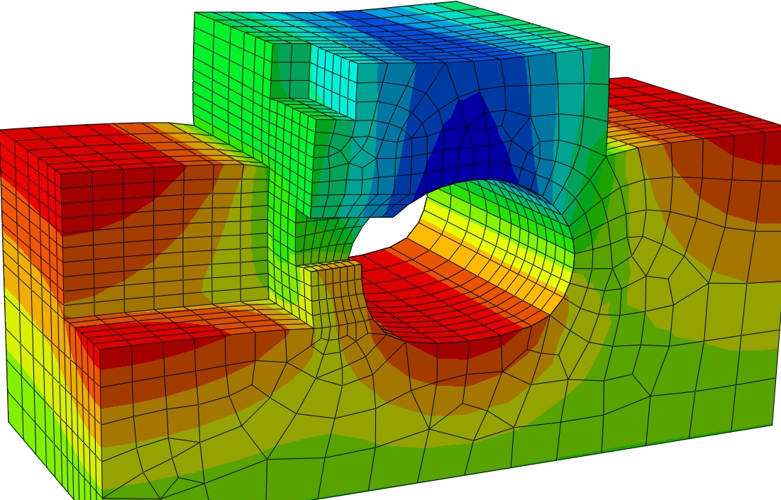
Opposite: Excavation sequence of the cavern in soft ground, geologic profile of the cavern's west part with soft ground shown in goldenrod, 3D FEA (Abaqus) of the cavern section in rock with two existing basement excavations, adjacent access shaft and temporary adit.
Canmore Dam
Town of Canmore, AB, Canada (2016)
A rockfill dam was designed to impound debris floods along Cougar creek near the Town of Canmore, which cause widespread damage to communities, bridges and highways located further downstream.
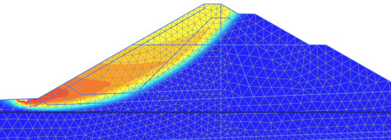
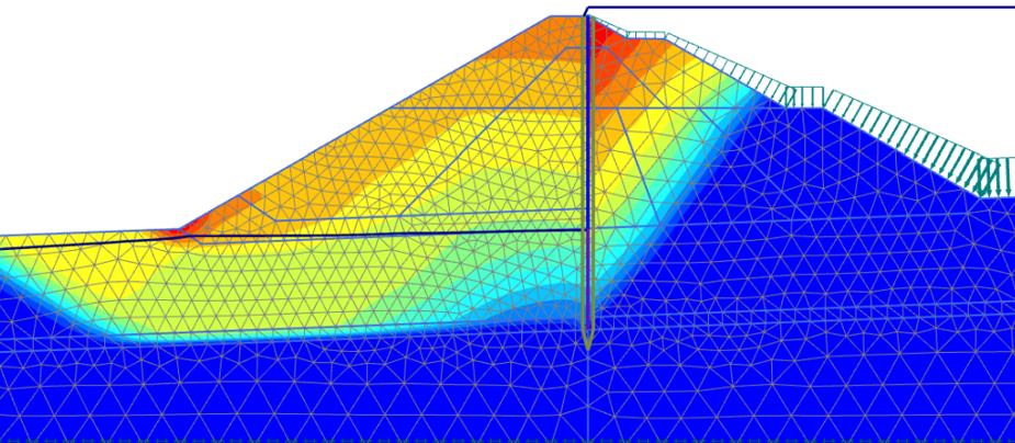
♦34 m high dam embankment of crushed stones with filter layers behind the cut-off wall for drainage. The dam is overtoppable along the middle third of the crest length to allow for extra discharge capacity in case of emergency. The downstream slope along this length was covered with heavy stone pitching in a thick reinforced concrete bed.
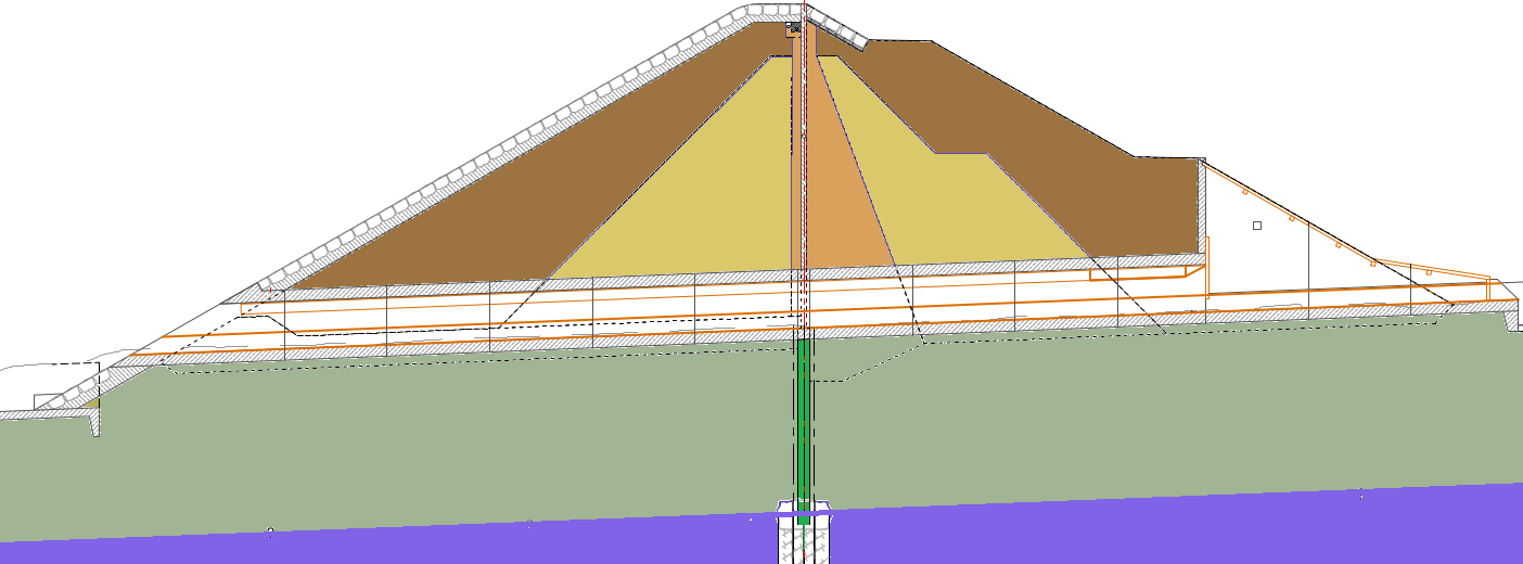
♦Cut-off wall made by secant piles below grade socketed into bedrock. Above grade the cut-off is 0.50 m thick reinforced concrete wall poured in several lifts.
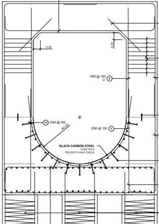
♦Outlet culvert 3.5 m wide x 4.5m high inside dimensions for the main discharge through the dam. Movement joints along the side walls and top slab allow for differential rotation between neighboring segments under the embankment's weight. A diversion tunnel through the rock abutment was also prepared for the bid as an alternative.
Opposite: Downstream slope stability for the dry case and full storage, Outlet culvert cross section, Dam cross section through the outlet culvert.
Blue Plains CSO Shafts
DC Water Clean Rivers Project, Alexandria, VA (2012)
The first part in the Clean Rivers Project in Washington DC, the design-build Blue Plains CSO project included five large drop and processing shafts in soft ground adjacent to the Potomac and Anacostia Rivers, in addition to a 4 miles long 23 ft inside diameter TBM-driven tunnel.
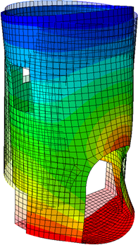
♦Design of the cast in-place final lining for the 51 ft ID and 135 ft deep Bolling Air Force Base Shaft. Design included an 8 ft thick tremie base slab connected to the outside diaphragm wall to resist uplift, CIP walls with two large openings at the bottom for tunnel passage, and temporary shaft cover. Detailed finite element shell analysis of for the upper and lower openings including seismic loads.
♦Design of cast in-place base slabs as inverted domes for the 140 ft ID Dewatering Shaft and 80 ft ID Screening Shaft to resist 190 ft uplift.
♦Numerical analysis of part of the diaphragm wall with substantial lateral offset between the adjacent panels due to construction imperfections. Use of non-linear material model for concrete to evaluate the effect of plastic yielding under high concentrated stress on the wall carrying capacity.
Above: Inside view of the Dewatering Shaft during construction after reaching a temporary invert level, stress concentration on a vertical joint between stepped diaphragm wall panels.
Opposite: Shell models of the upper and lower parts of the BAFB Shaft, Inverted dome base slab of the Dewatering shaft.
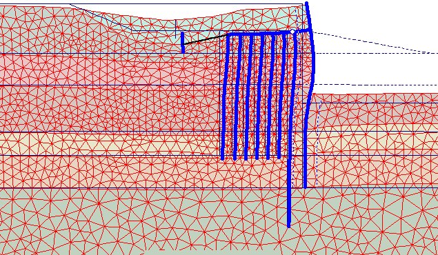
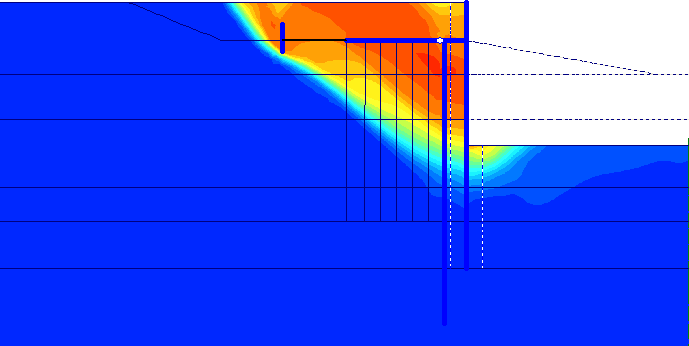
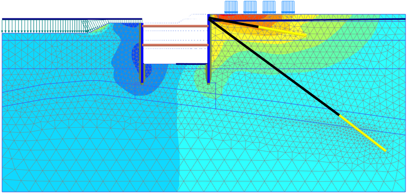
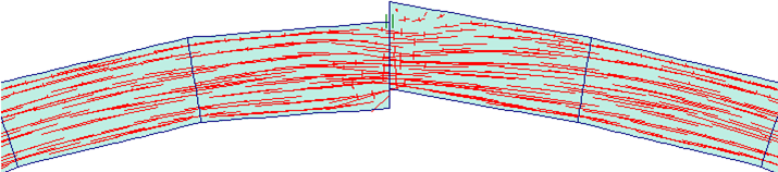
Above: Soil-structure FEA predicted excessive deformations corresponding to those observed on site, failure wedge already developing at service stage.
Freeport Wharf 7
Port Freeport, TX (2011)
Forensic analysis of the constructed Berth 7 (designed by others), which had experienced substantial horizontal displacements of the earth retaining structure and a large subsidence of the ground surface behind.
♦The structure consisted of a sheetpile with 45 ft design dredging depth, relieving platform on auger-cast piles, and front counterforted wall to retain 15 ft embankment height above.
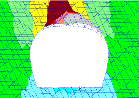
♦FEA indicated that the structure was already unsafe at 70% of the design dredging depth due to insufficient size and extension of the deadman anchor, which was laid inside the failure wedge.
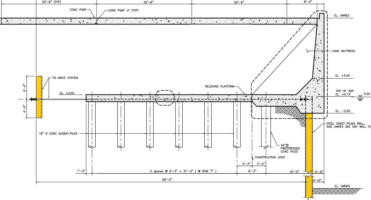
Above: Berth cross section as designed by others. Sheetpile wall, deadman anchor, relieving platform and upper retaining wall.
Mitchell Interchange Underpasses
Milwaukee, WI (2010)
Three 60 ft wide and 580-750 ft long underpasses were constructed for the Mitchell interchange along the I-94 North-South Corridor.
♦Abutments are one-pass retaining wall made by secant piles with a capping beam to support the superstructure. The piles were covered by facing concrete elements with permanent drainage. Bridge deck is 45W bulb-T precast prestressed girders and a CIP RC topping slab. Construction was not top-down to accommodate Contract0r's preferences and included a cantilever stage for the abutments.
♦Design work included soil-structure interaction analysis of the whole structure with construction stages and seepage analysis.
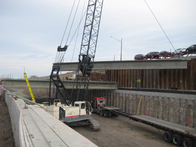
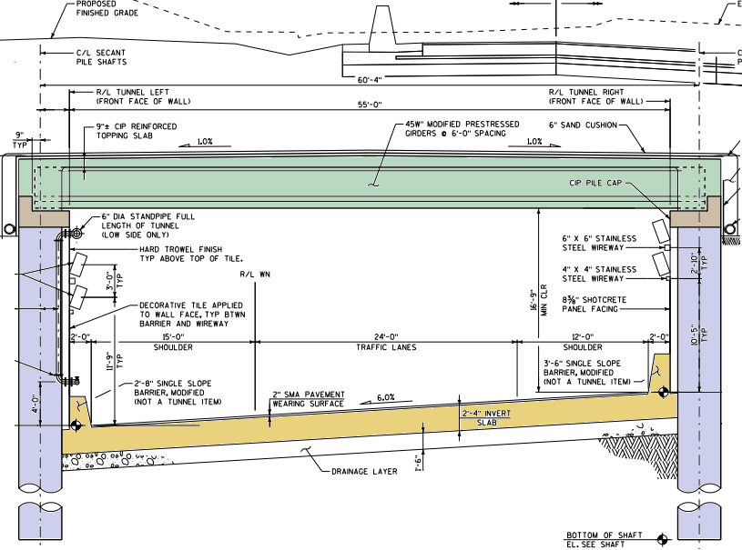
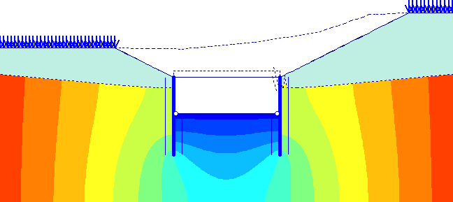
Above: Typical underpass cross section, seepage analysis during construction.
Opposite: Installation of the precast bulb-T girders on the finisded capping beams.
Lake Mead Intake 3
Las Vegas Deep Water Intake, NV (2009)
The intake runs under Lake Mead about 10 miles northwest of the Hoover Dam and 450-500 ft below high water level. Design review, independent analyses and checks on behalf of the Owner (South Nevada Water Authority) for all project components:
♦Submerged intake riser that was prefabricated onshore, floated to the site, sunk to position, connected to the segmental tunnel lining, and embedded in tremie concrete for lateral and floatation stability.
♦2.9 miles long segmentally-lined tunnel running under the lake and carrying 17 bars of external water pressure. The segmental lining is 20 ft inside diameter and 14" thick (universal ring, 5 segments + key).
♦550 ft deep access shaft excavated in rock with two adits at different levels for intermediate pump stations. TBM launching cavern and starter tunnel at the base of the shaft.
Above: transverse and axial (ring) stresses through the segment thickness at the radial joint in case of extreme eccentricity due to birdsmouthing.
Opposite: tensile ring stresses in tremie concrete above the intake tunnel due to backfill grout pressure, shell model of the intake riser under external pressure, analysis of the tunnel face stability under squeezing external pressure with no slurry pressure.
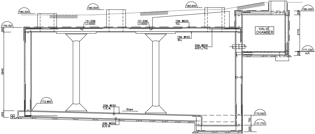
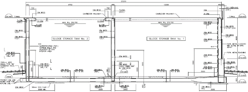
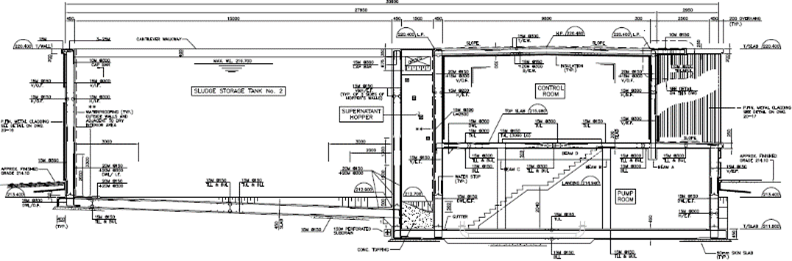
Ground Tanks
Multiple Locations, Ontario, Canada (2004-2006)
Opposite: Sludge storage tank, Parry Sound Waste Treatment Plant
Below: Underground tank in Lambton.